Current-driven magnetic domain-wall logic.
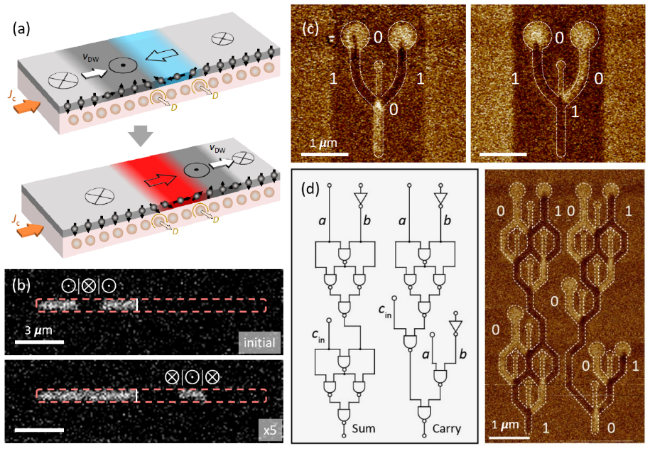
Current-driven magnetic domain-wall logic. (a) Schematics of a domain-wall inverter (NOT gate). (b) Magneto-optical Kerr effect images of a domain-wall inverter (white line) prior and post application of a series of electric pulses. (c) Magnetic force microscopy images of a NAND gate. (d) Left panel: Sketch of a full adder gate. Right panel: realization of the full adder gate with “a=0” and “b=1” inputs resulting in “Sum=1” and “Carry = 0”. Reproduced from [6].